
Fine Foam Blaster Accoutrements
Fine Foam Blaster Accoutrements
Consider yourself warned, the following modification guide illustrates an irreversible modification to the Nerf Stryfe, attempt these modifications at your own risk.

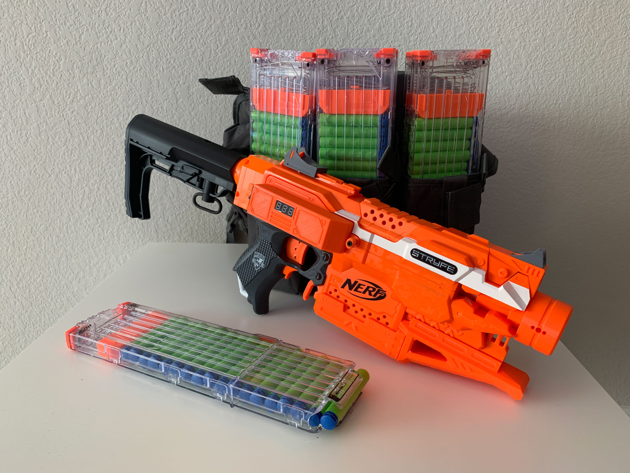
Prototypes, 3s full-auto OJ Stryfes in both full-length and half-length variants.
The build outlined here is based on my prototype 3s full-auto Stryfe

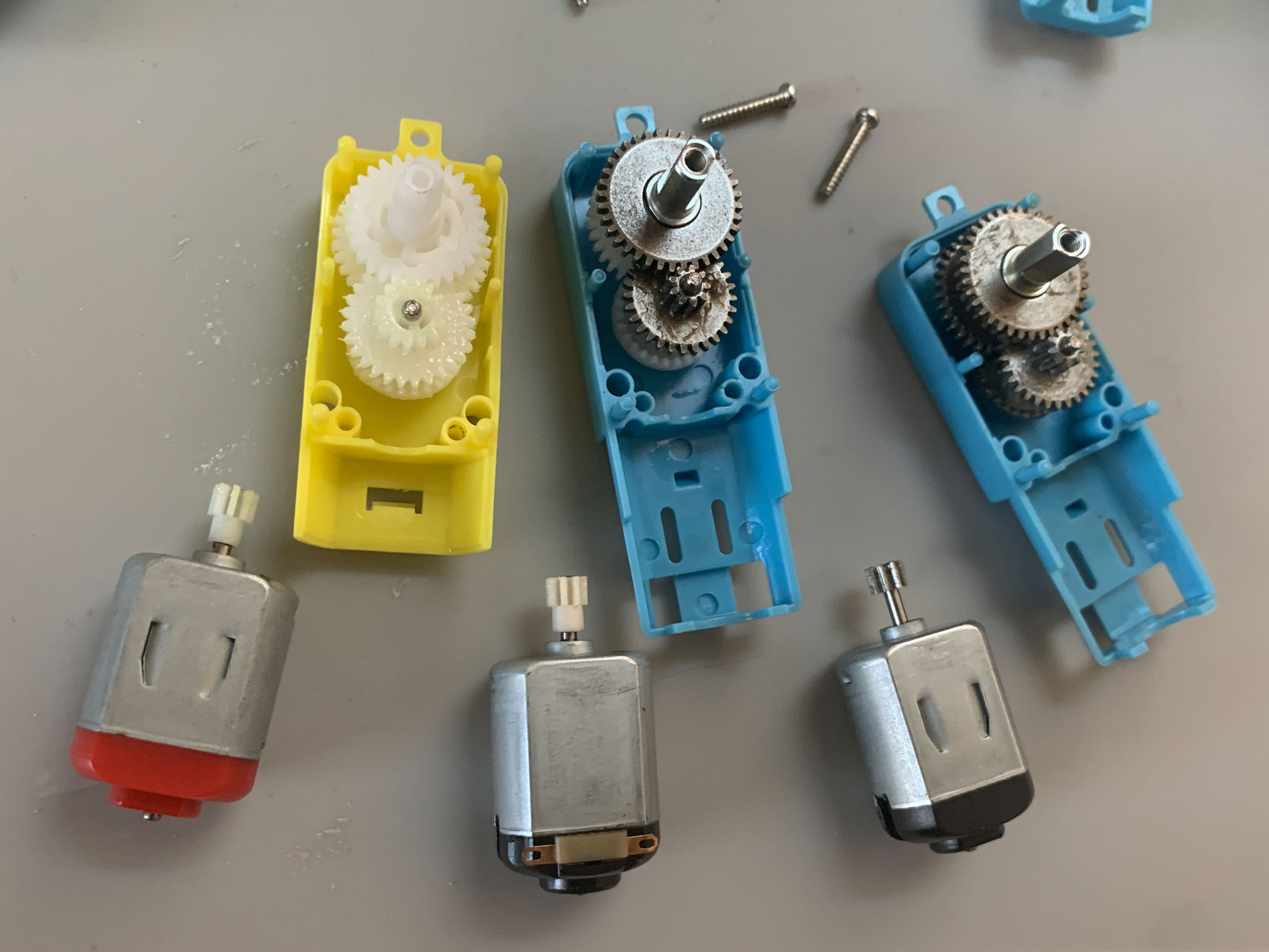
Single axial TT gearmotors - 3 variants; 1:48 all plastic, 1:90 half metal, 1:90 all metal.

Installing the components for the full-auto mechanism will require modifying areas of the shell to allow for proper clearance of moving parts. The shaft of most 130 motors will be too long to be correctly seated in the gearmotor and will need to be trimmed. The axle on the gearmotor is too long and must be trimmed to be flush with the face of the crankwheel.
Start by removing all the stock electronic components.
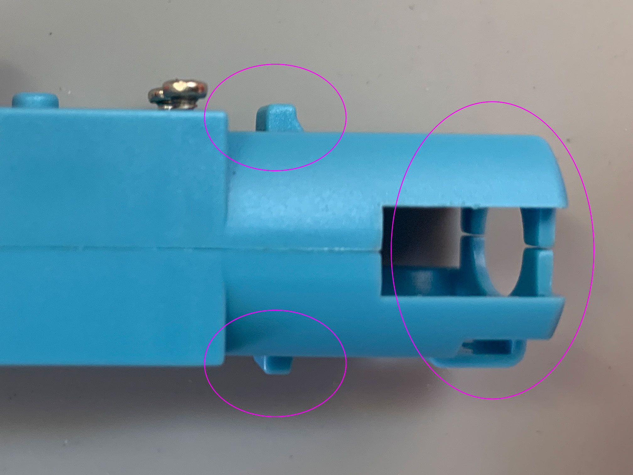
This side of the shell will require the most modification. One last warning, once these modifications are made they are irreversible, your Stryfe will no longer have portions of the shell that the semi-auto pusher arm requires to operate correctly. To create clearance for the gearmotor to seat properly remove the topmost rib just above second rib that is above the main post that the pusher slides along.
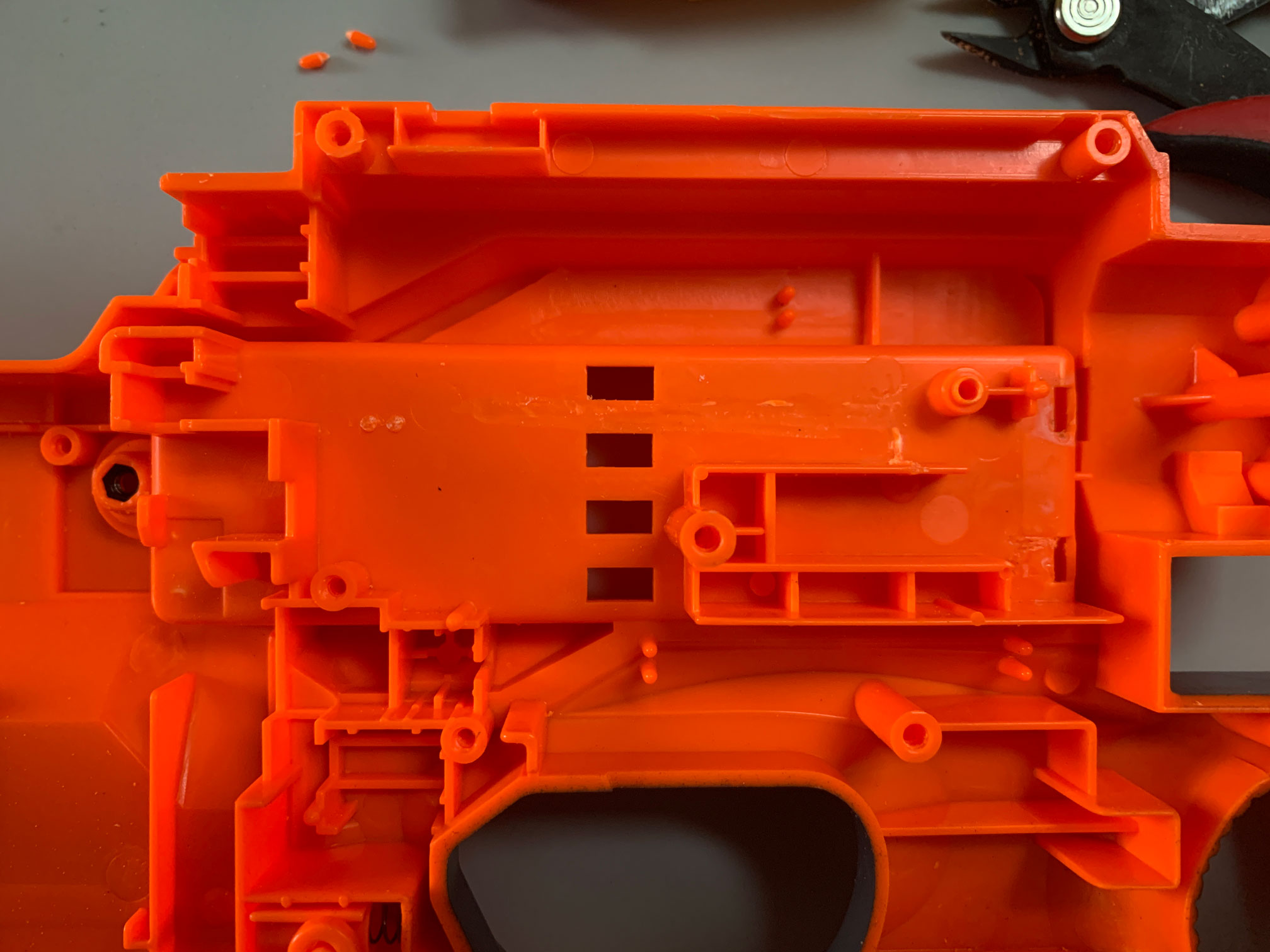
Remove the rib as shown here to allow for the gearmotor to seat in the shell. Remove the little wire stay nubs too.
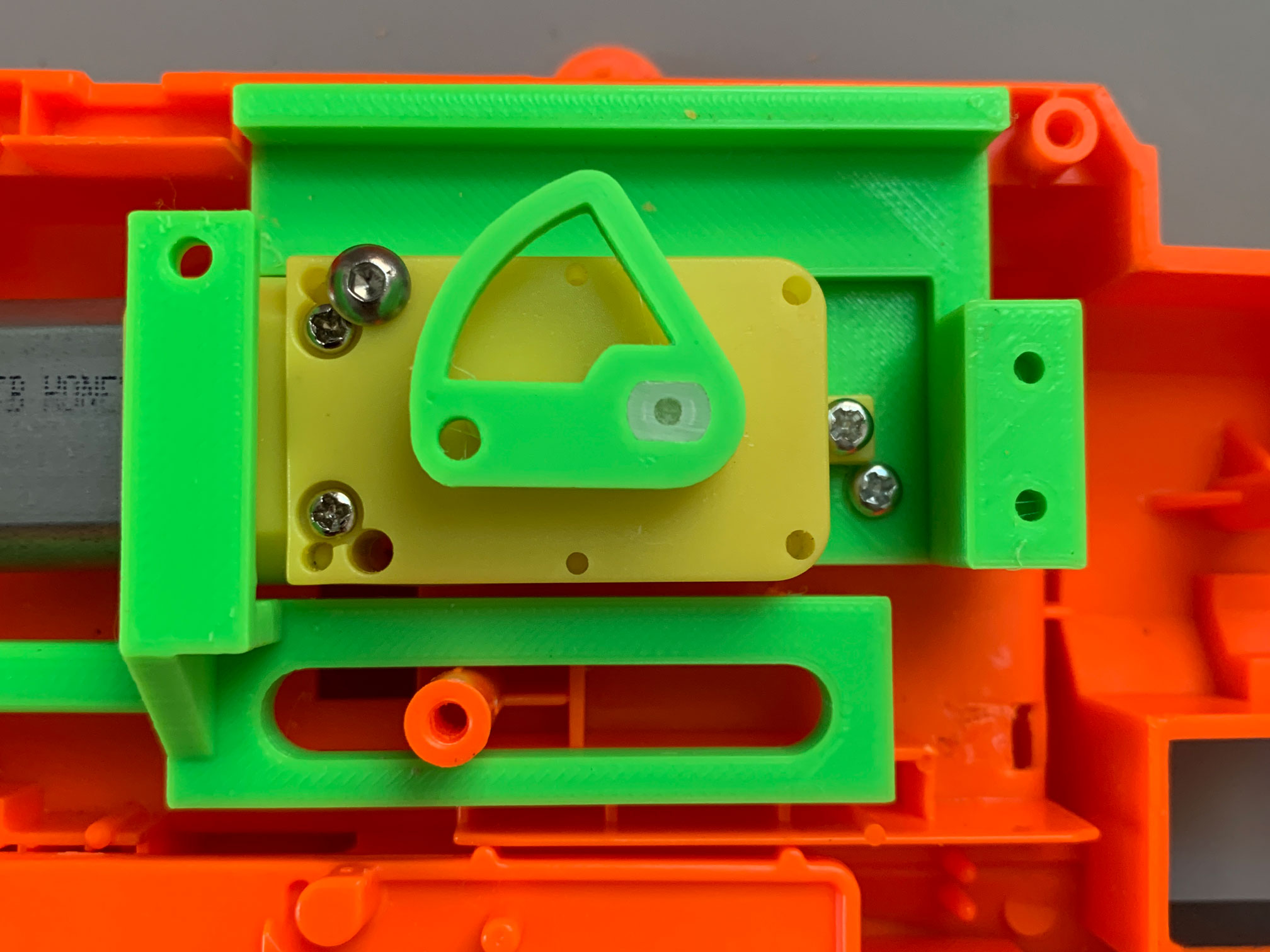
To use the revswitch mount remove the lower right portion of the existing revswitch mount and trim the screw post so it's flush with the top of the mount. The trigger switch mount just drops in on top of the existing webbing.

Remove these areas of the shell around the original rev trigger mounts to allow room for new 3d printed switch mounts to drop in.
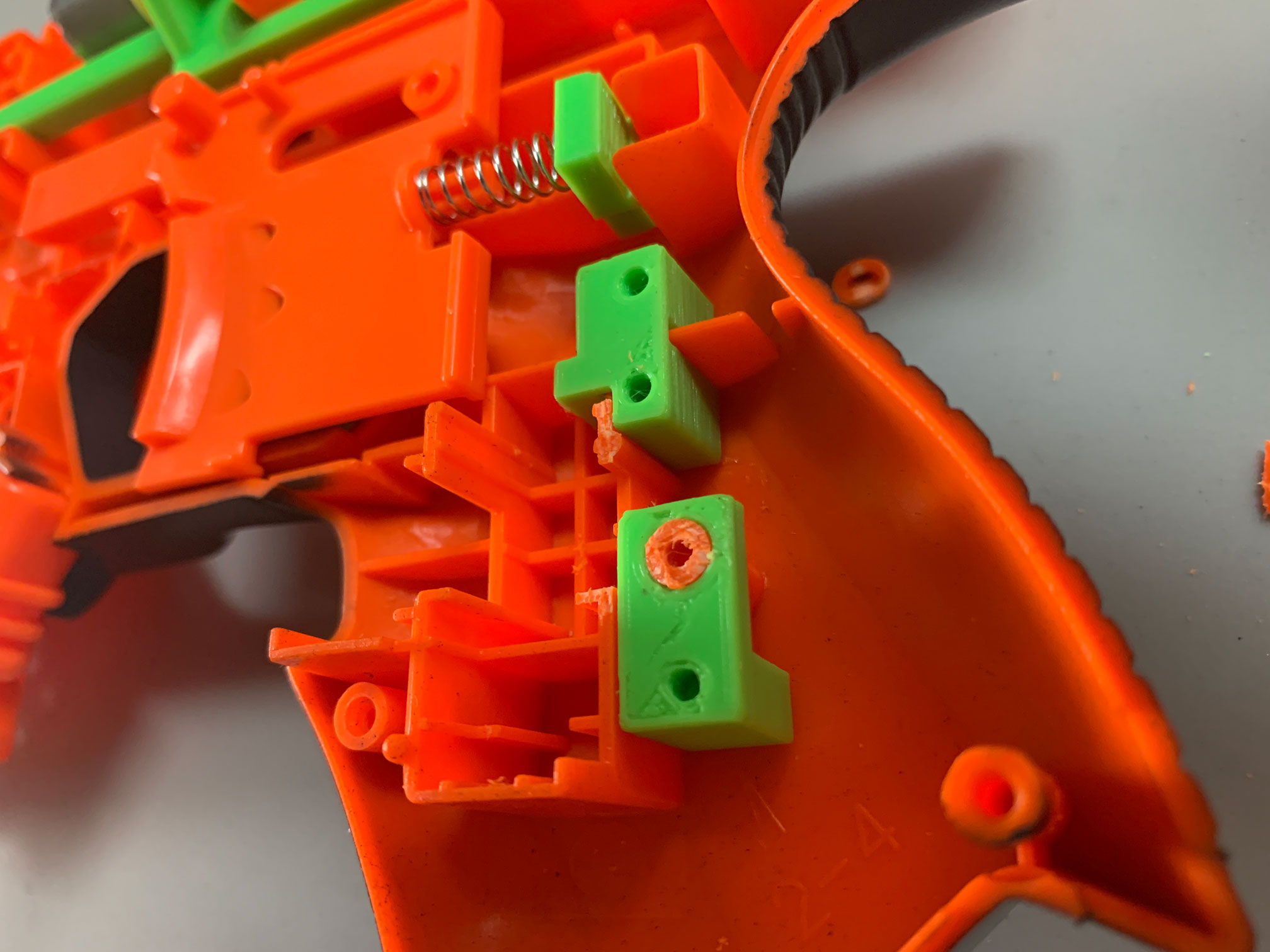
Don't trim too much, the trigger switch uses the existing webbing to position itself. You should trim the screw post down so it's flush with the 3d printed switch mount. It's a good idea to glue these in place.

The spring cup is also optional, I like a springy trigger if you do to it's probably worth trying out.
You may or may not encounter clearance issues in 3 places on the left side of the shell. To allow the pusher arm full range of movement shave down the side area that is furthest toward the front just on the other side of the jam door access area. Further back, opposite of the crankwheel shave down the area where the m3 screw from the crankwheel rubs against the shell. Also, opposite of the crank wheel shave down the inner-top of the shell where the top the crankwheel/connecting rod orbit rubs. If you want to be more precise close the blaster up run the pusher cycle and rub marks will appear opposite the crank wheel, the forward area should be shaved before closing up to prevent possible damage to any pusher components.
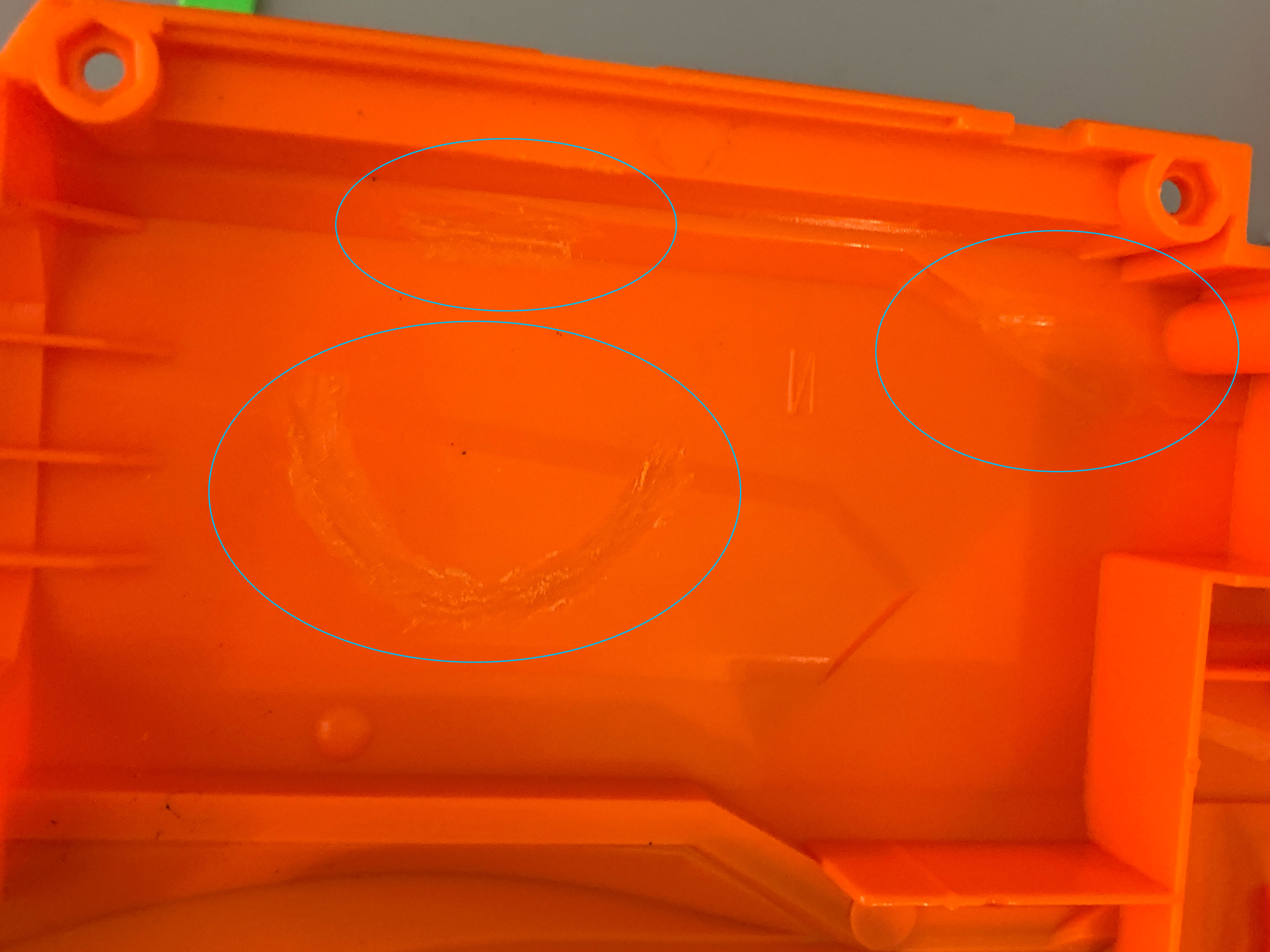
Be careful when shaving these areas down, it doesn't take much to create enough room for clearance on this side. It might be better to close up and let the crankwheel rub, giving a clear indication of what needs to be shaved.
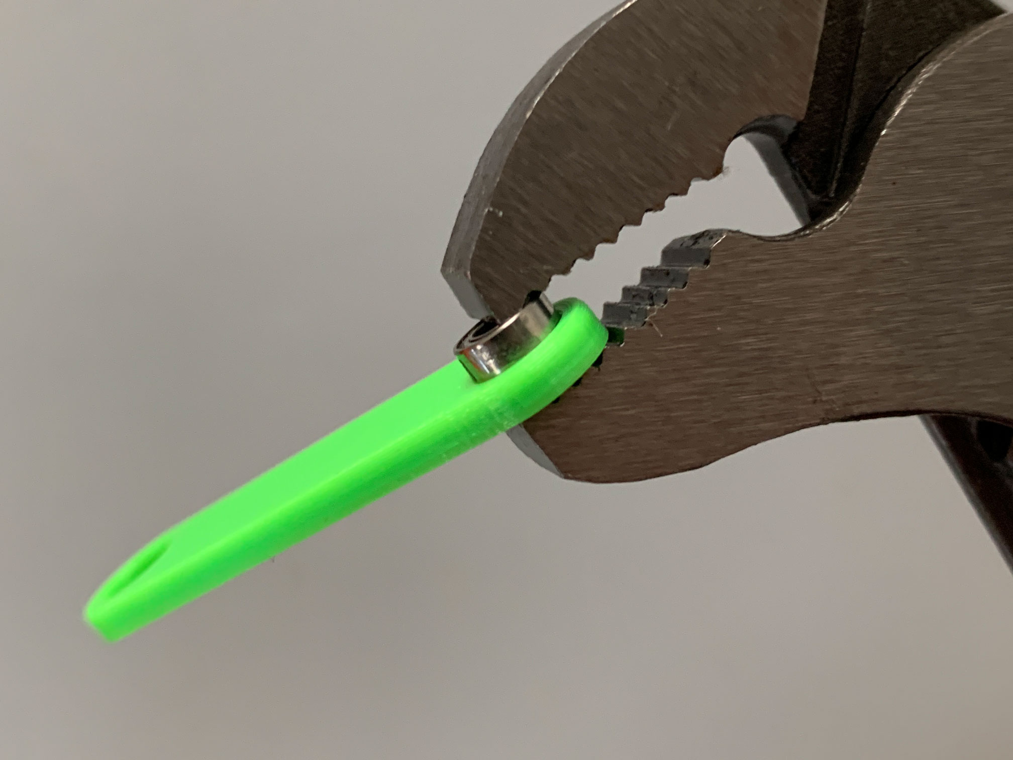
The pusher motor shaft should be trimmed to 8mm, you can use the printed motor shaft guide if you are using a 130 size motor. The motor used in the test build is an MTB Honeybadger with a 10mm shaft. When trimming, it's better to be too long, go slow and remember to chamfer the end of the shaft to aid in sliding the pinion gear on. You will need the pinion gear found on the motor that comes with the TT gearmotor. The best method I've found for removing the pinion is to pry up with a pair of wire cutters, just keep scooting the jaws of the wire cutter forward as the motor shaft slides up to maintain leverage. I've found that the pinion doesn't pop off until the shaft has been pulled really far out of the housing, removing the pinion will destroy the included motor. Gently tap the pinion on your pusher motor and check for proper alignment when seated in the gearmotor body.
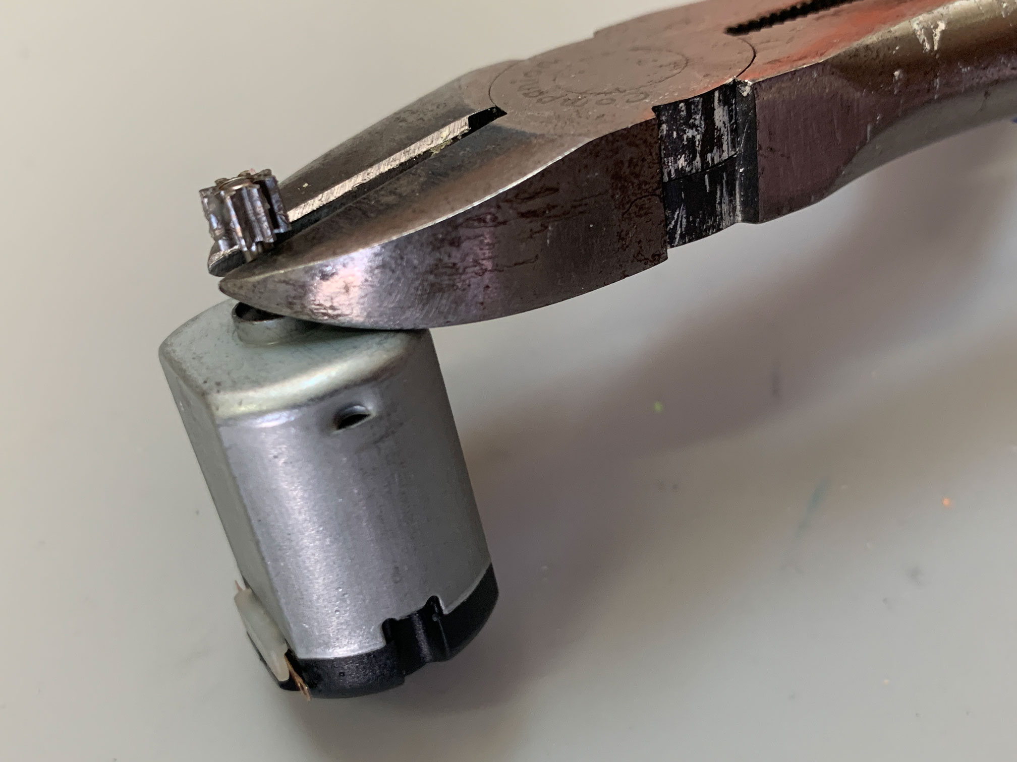
A pair of wire cutters make a good tool to remove the metal pinion from the original motor. Pry up, and scoot the shaft deeper into the jaws to maintain leverage.
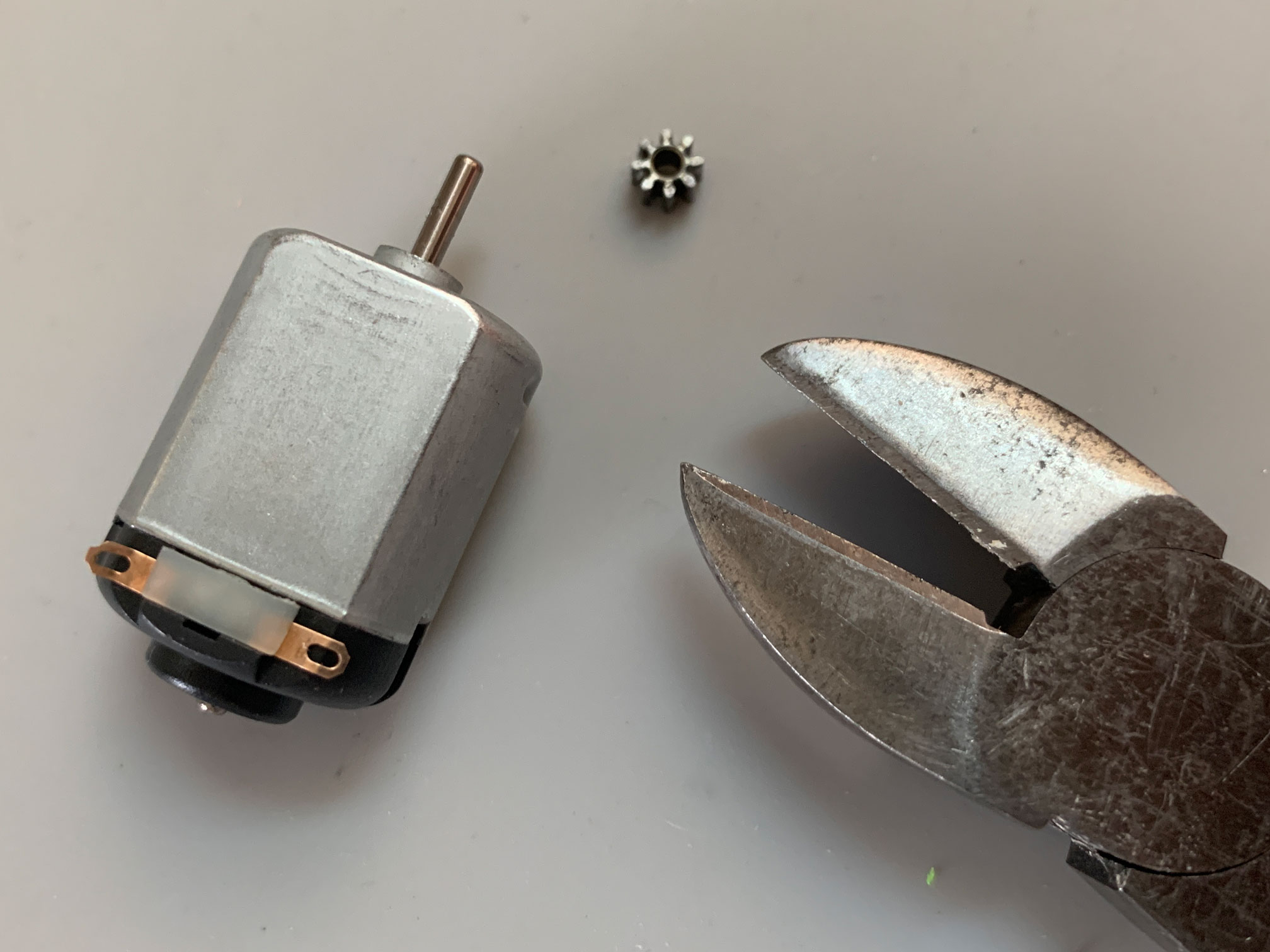
The pinion usually pops off when the motorshaft has been pulled up quite a bit.

The motor shaft on the pusher motor (an MTB Honeybadger in this case) should be trimmed to approximately 8mm, use the motor shaft trim guide to get a better idea of where to cut.

Don't forget to chamfer the end of the shaft to allow the pinion to slip on.
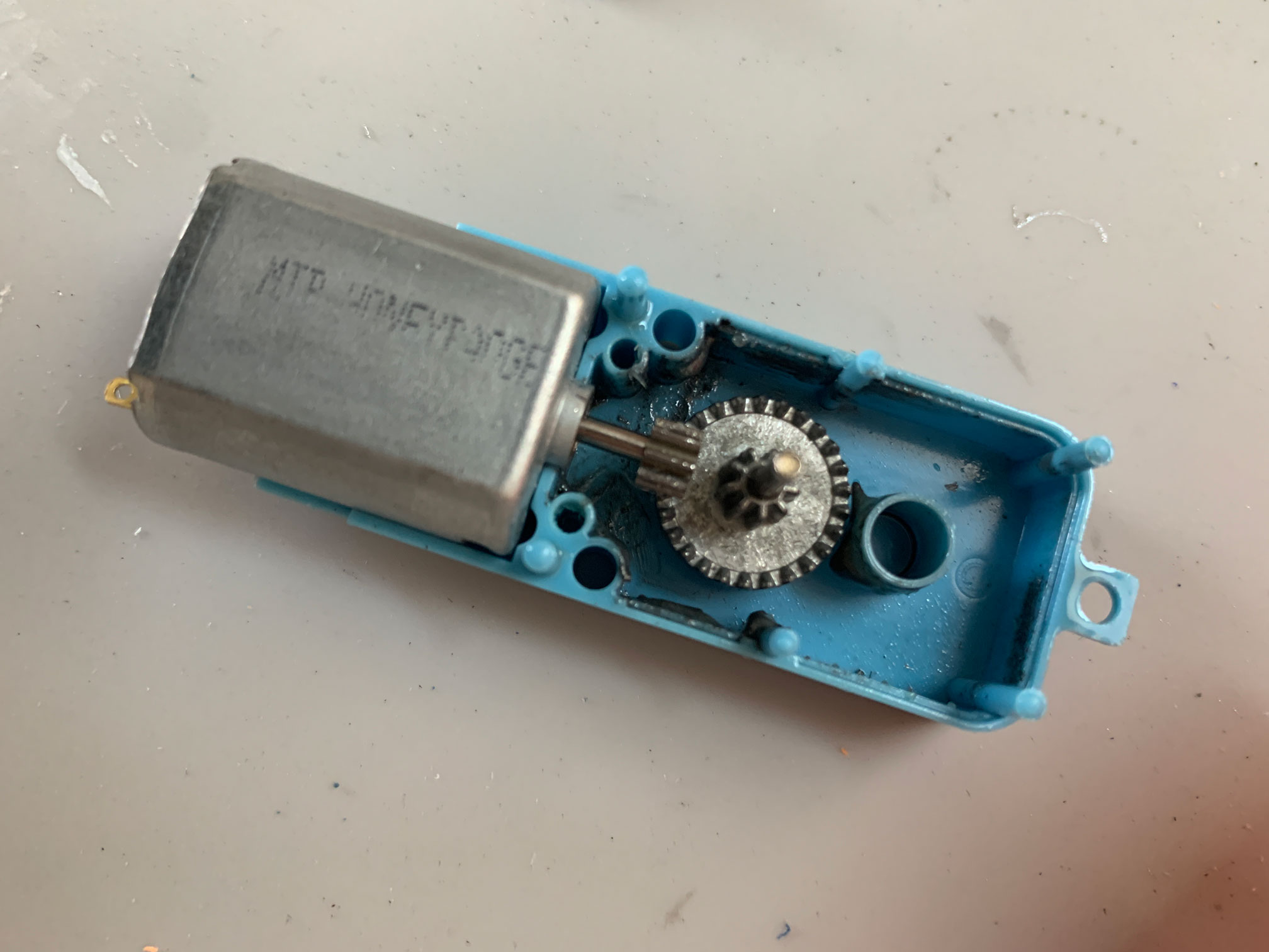
The position of this pinion is key to the life of your metal gears, get it as close to the original location as possible. The goo in this case is comprised partly of shredded metal that was the result of a poorly aligned pinion.
The gearmotor axle is too long and must be trimmed flush with the top the crankwheel to allow for the connecting rod/crankwheel assembly to rotate. You should use the printed axle trim guide to bring its length down to 4mm. Chamfer the edges of the axle to aid in mounting the crankwheel.

Use the 3d printed axle trim guide to get the shaft to the correct length.

Cut the axle so it's flush with the top of the guide.
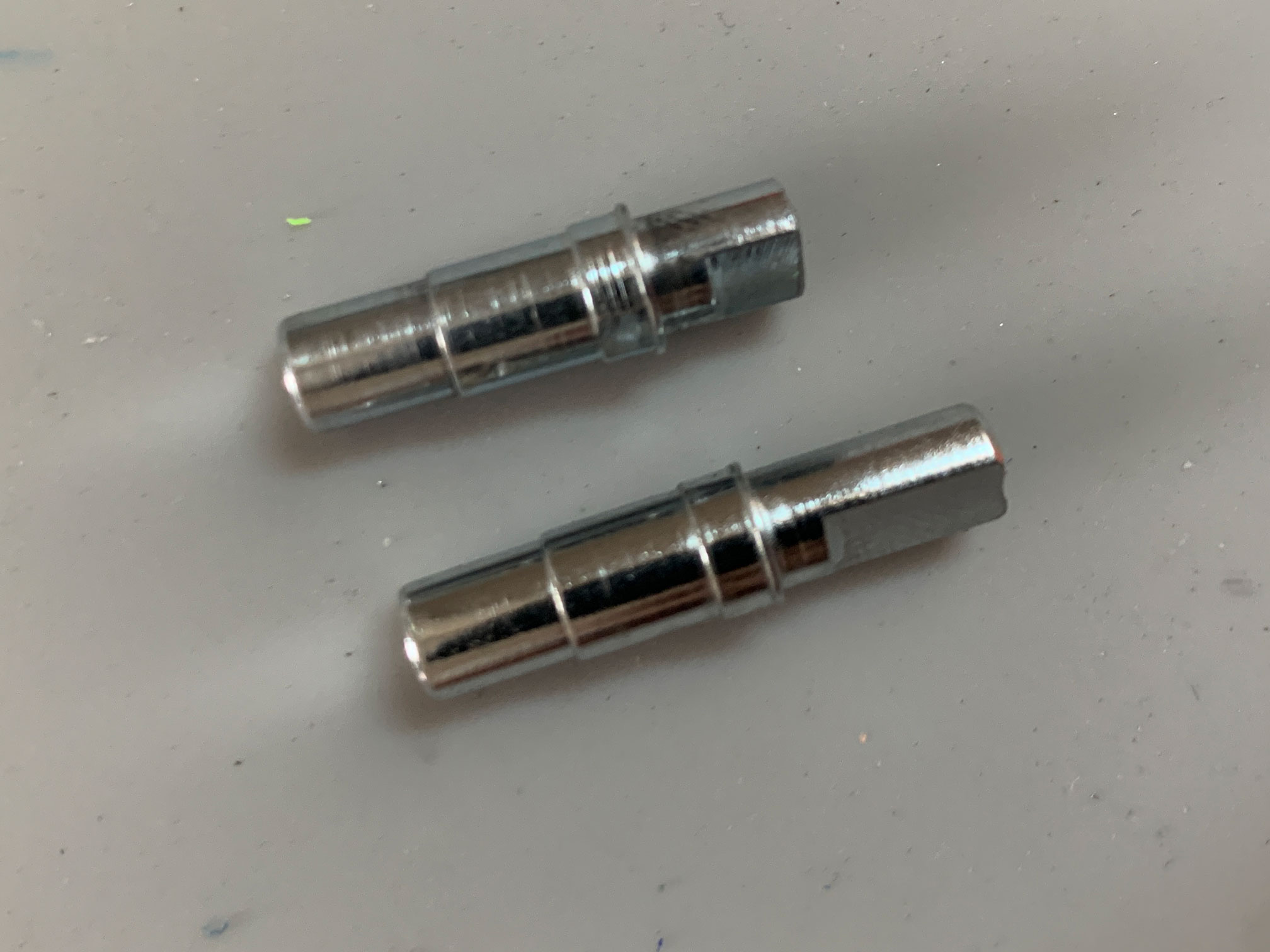
Before and after TT gearmotor shaft.

A properly aligned pusher motor with all gears back in the case.
If you are using the 1:90 variant remove the back of the gearmotor case to properly seat the pusher motor. For all variants, tabs on the top and bottom of the case will also need to be shaved to allow the gearmotor to lie flat in the shell and to allow for clearance of the pusher arm.
Shave off these tabs on the outside of the gearmotor case. You'll also need to remove the rear section to make room for the new pusher motor.
Use the stock voltage limiter mounting point to anchor the gearmotor mount to the blaster shell. Any short interior screw will be re-used to screw the gearmotor down on one side and 1 m3x20 button head screw to secure the other side of the case. Mount the crankwheel to gearmotor axle, press the bearings into the connecting rod, and drop the pusher arm in remembering to use the collet piece to hold the pusher down. Use plastic friendly lubricant on all pusher arm surfaces that will move along the ribs in the shell or ride along the main screw post. Connect the crankwheel and pusher arm to the connecting rod with m3x6mm button head screws, m3 washers should go between the rod/arm and rod/crankwheel connecting points. Wiring is similar to what is found in a Rapidstrike rewire, the microswitch is tripped by the crankwheel alternating the pusher circuit to ensure that the pusher returns when the trigger is released mid-cycle. To prevent runaway on 3s you must incorporate a buck converter to step down voltage to the pusher motor. Step the voltage down until the runaway stops. Only 3s has been tested so far, on 2s builds the use of a buck converter may be unnecessary.

The gearmotor mount drops in, anchored where the stock voltage limiter screws in. The other side of the shell provides a pressure fit to fully secure the mount.
1 re-used short interior screw anchors one side of the gearmotor, on the other side 1 m3x20 secures the case to the mount.

Connecting rod, 2 3mmx6mmx2.5mm bearings, 2 m3X6mm button head screws, and 2 m3 washers.
Press the bearing into the connecting rod, I'm using a small pair of tongue and groove pliers here.

The m3 washers should go between the rod/arm and rod/crankwheel connecting points. I suggest placing them shinny side down.

Be sure not to over tighten the m3x6mm button head screws, there should be a good amount of slack between the rod/arm and rod/crankwheel connecting points.

2 switch auto-pusher wiring diagram, with a buck converter incorporated, stepping down the voltage sent to the pusher motor to prevent runaway in the pusher mechanism.

In this part of the shell using 18AWG wire will help with the small amount of space you have to route wiring. Be sure to make room for the buck converter, with enough slack so that the voltage adjustment is still accessible.
Be sure to test before closing up the shell.
Short story is it works, but needs lots of optimization. Future updates will be coming on the half length variant.
The insane DPS in this clip is a result of the 1:48 gear ratio found in the plastic variant of the TT gearmotor. Be warned, runaway is nearly impossible to prevent at these speeds.
Overall I'm fairly happy with the prototype, ROF hangs somewhere between 8-9 DPS and FPS numbers are in the high 130s under sustained operation with a mid-crush flywheel cage, the crank-slide pusher should prove more reliable over spring-loaded rack and pinion style pushers. With this approach there is no spring-loaded pusher slamming into the primary pusher post continually - which eventually leads to cracking that post and a dead Stryfe - or maybe one that will need a good amount of glue to bring back into full operation. While both the 1:48 and 1:90 variants of the TT gearmotors do work, I've been able to achieve more consistent results with the all metal 1:90. With the 1:90 it was easier to tune out the runaway, with the 1:48 while it is very satisfying to crank up the DPS there was no reliable way to control runaway. I strongly suggest using the all metal or half-metal 1:90 TT gearmotor over the 1:48.
Chronograph testing results were recorded with a 3s lipo @11.8v, 18 round Nerf mags, and Adventure Force darts. I cycled 7 mags total or 126 darts.
Sustained 136FPS @ 8DPS feels like a good starting point for further optimization.

